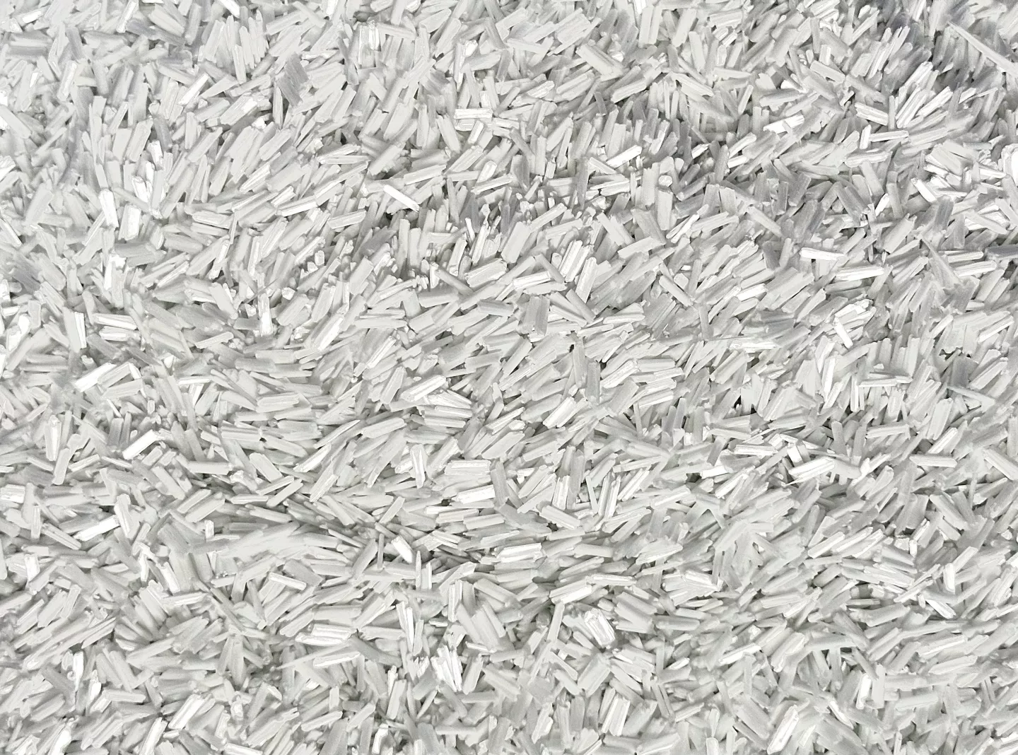
Glass Filled Nylon Injection Molding is a highly engineered process used to produce high-performance components made from glass fiber reinforced nylon such as PA6 GF and PA66 GF. With 15–50% glass fiber content, these materials deliver outstanding stiffness, strength, and dimensional stability—often replacing metal parts in demanding structural applications.
Compared with unfilled nylon, glass filled grades require tighter control of moisture, melt temperature, shear, and gating design to achieve consistent mechanical properties. This guide covers material behavior, processing parameters, design rules, troubleshooting, and real-world case studies.
How Glass Fiber Reinforcement Changes Nylon Processing Behavior
Glass fibers change how nylon flows and cools during molding. They increase stiffness and stability but also make the melt harder to process:
- Higher Melt Viscosity: Fibers resist flow, requiring higher injection pressure.
- Directional Strength (Anisotropy): Fiber alignment strongly affects warpage and mechanical performance.
- Faster Heat Transfer: GF compounds cool faster, often requiring higher mold temperatures for surface quality.
- Increased Tool Wear: Glass fibers are abrasive; hardened steel (H13 / 1.2344) is recommended.
- Fiber Length Sensitivity: High shear breaks fibers and reduces strength.
Molding GF nylon requires controlling shear, preserving fiber length, and maintaining moisture stability—not simply increasing melt temperature.
📌Recommended Reading
1. Why Choose Glass-Filled Nylon for Injection Molding?
Glass fiber reinforcement transforms nylon into a structural-grade engineering plastic with the following advantages:
- High Strength-to-Weight Ratio: Tensile strength can reach 190–245 MPa.
- Excellent Dimensional Stability: Shrinkage decreases to 0.1–0.5%.
- Thermal Resistance: HDT up to 210–250 °C depending on grade.
- Superior Creep Resistance: Maintains integrity under load.
- Chemical Resistance: Good resistance to oils, fuels, and lubricants.
- Metal Replacement: Enables lightweight, cost-effective alternatives to aluminum or zinc die-cast parts.

📌Recommended Reading
2. Limitations and Design Challenges of PA GF Compounds
GF nylon performance comes with several manufacturing considerations:
- Higher brittleness compared with unfilled nylon.
- Abrasiveness toward screws, barrels, and molds.
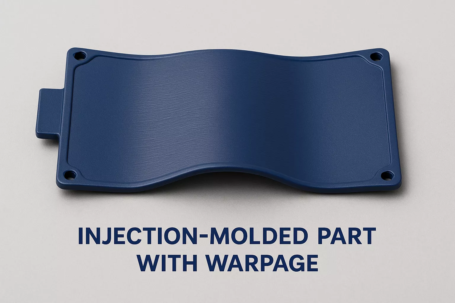
- Anisotropic shrinkage leading to warpage.
- Reduced flowability requiring higher pressure and optimal gating.
- Moisture sensitivity: Must remain < 0.2%.
- Surface fiber exposure if shear is excessive or mold temp is too low.
📌Recommended Reading
3. Key Material and Processing Properties Comparison (PA6 GF30 vs PA66 GF50)
The table below shows how two common glass filled nylon grades differ in practice:
| Category | Property | PA6 GF30 | PA66 GF50 | Key Difference |
|---|---|---|---|---|
| Mechanical | Tensile Strength | ~190 MPa | ~245 MPa | Higher GF → higher strength |
| Flexural Modulus | ~9,200 MPa | ~16,000 MPa | PA66 GF50 is extremely rigid | |
| HDT @ 1.8 MPa | ~210 °C | ~250 °C | PA66 enhances heat resistance | |
| Physical | Density | 1.38 g/cm³ | 1.59 g/cm³ | Higher GF → heavier parts |
| Processing | Moisture Requirement | < 0.2% | Critical to avoid hydrolysis | |
| Melt Temp. | 260–280 °C | 280–300 °C | PA66 needs higher melt temp | |
| Mold Temp. | 80–90 °C | Improves crystallinity & finish | ||
Key Takeaways:
- Higher GF % increases stiffness and heat resistance but decreases ductility.
- Moisture control (< 0.2%) is essential to prevent splay and hydrolysis.
- PA66 GF50 delivers maximum rigidity and heat resistance among standard PA grades.
📌Recommended Reading
4. Application Examples by Industry
- Automotive: Engine covers, intake manifolds, high-heat brackets.
- Industrial: Gears, pump housings, mechanical supports.
- Electrical & Electronics: Connectors, switches, housings.
- Consumer Products: Power tools, sports equipment, appliance mounts.
5. Design Guidelines to Minimize Warpage and Anisotropy
- Wall thickness: Maintain 2.0–3.0 mm uniformity.
- Radii: Use ≥ 0.5× wall thickness.
- Ribs/Bosses: Avoid thick intersections.
- Gate placement: Align with desired fiber orientation.
- Venting: 0.02–0.04 mm to prevent burns.
- Draft angle: Minimum 1–2°.
6. Optimal Processing Parameters for PA6 & PA66 GF
A. Material Preparation
- Dry at 130–140 °C for 3–4 hours.
- Moisture should be kept well below 0.2% before molding.
B. Temperature Management
- PA6 GF: 260–280 °C
- PA66 GF: 280–300 °C
- Mold Temp: 80–90 °C
C. Injection & Holding
- High injection pressure for dense packing.
- Moderate speed to preserve fiber length.
D. Tooling
- Use hardened steel (H13 / 1.2344).
- Ensure balanced cooling to reduce warpage.
E. Process Stability
- Limit residence time and purge regularly.
- Ensure gate balance & moisture stability.
7. Common Defects and Troubleshooting
| Defect | Cause | Solution |
|---|---|---|
| Warping | Fiber orientation / uneven cooling | Improve cooling balance; adjust gate |
| Splay | Moisture > 0.2% | Increase drying; purge properly |
| Fiber Exposure | High shear / low mold temp | Reduce screw speed; raise mold temp |
| Brittleness | Overdrying / excessive shear | Reduce back pressure; adjust speed |
| Tool Wear | Abrasive fibers | Use hardened or coated inserts |
8. Case Study – Engine Bracket Replacement
A Tier-1 automotive supplier replaced a die-cast aluminum engine bracket with PA66 GF50, achieving:
- 45% weight reduction
- Equivalent structural durability
- 18% tooling and production cost savings
Gate repositioning and hardened steel inserts enabled low warpage (<0.1 mm) and excellent heat-cycle performance.

📌Recommended Reading
9. Final Recommendation
PA6 GF30 works well where you need decent toughness and more complex flow paths, while PA66 GF50 is better suited for highly loaded brackets or parts running at elevated temperatures.
FAQ – Glass Filled Nylon Injection Molding
1. What is glass filled nylon?
Glass filled nylon is nylon reinforced with 15–50% chopped glass fibers, improving strength, dimensional stability, and heat resistance.
2. What is the difference between PA6 GF30 and PA66 GF50?
PA6 GF30 offers better flow and toughness; PA66 GF50 has significantly higher rigidity and heat resistance.
3. Why does glass filled nylon warp?
Fiber alignment causes anisotropic shrinkage. Warpage occurs when flow direction and cooling are unbalanced.
4. What drying conditions are required?
Dry PA6/PA66 GF at 130–140 °C for 3–4 hours with moisture maintained below 0.2%.
5. Can glass filled nylon replace metal?
Yes. PA6 GF and PA66 GF are widely used to replace aluminum and zinc die-cast parts with 40–50% weight reduction.
Ardlon® Solutions – Global Support
Our Ardlon® PA6 and PA66 GF compounds support clients across Asia and North America. We provide material selection, tooling guidance, and sample testing support.
📞 Contact us today to connect with a technical consultant or request a sample.
